Enigma Ring Settings on the Commodore 64
By Michael Doornbos
- 16 minutes read - 3270 wordsWe’ve been ignoring ring settings. In The Math Behind Enigma we counted them as part of the keyspace but didn’t explain how they work. In the emulator article we said “it’s not hard to add” and moved on. In the cracker we skipped them too, keeping the search space at a manageable 5.9 million candidates. Time to deliver on those promises.
Ring settings (Ringstellung) were part of every real Enigma key sheet. Each rotor had a movable alphabet ring that the operator could rotate relative to the rotor’s internal wiring. The ring didn’t change the wiring itself. It changed the relationship between what the operator saw through the window and what the wiring actually did. Turn the ring one position and everything shifts: the letter visible at a given internal position, and where the turnover notch sits.
Two effects, both small in code. But they multiply the keyspace by 17,576.
What Changes
In the emulator, the rotor pass math looked like this:
entry  = (letter + position) mod 26
result = table[entry]
output = (result - position + 26) mod 26
With ring settings, each rotor has a ring value (0-25) that offsets the wiring from the visible position. The math becomes:
entry  = (letter + position - ring + 26) mod 26
result = table[entry]
output = (result - position + ring + 26) mod 26
The ring subtracts on entry and adds on exit. The ring shifts the alphabet relative to the wiring. If the ring is set to B (1), what was wired as position 0 is now labeled as position 1. So we undo that shift before looking up the wiring, then put it back after.
The stepping logic also changes. Each rotor’s notch is physically attached to the ring, so turning the ring moves the notch with it. The notch that was at position Q (16) with ring A (0) moves to position P (15) with ring B (1):
effective_notch = (notch - ring + 26) mod 26
That’s it. Two lines of pseudocode changed for the rotor pass, one for each notch check.
BASIC Changes
Starting from the emulator’s BASIC code, we need to add ring settings to the configuration and modify two subroutines. Here are the changed and new lines:
695 REM RING SETTINGS (0=A, 25=Z)
696 DIM RS(2)
697 INPUT "RING SETTINGS (AAA)";RS$
698 RS(0)=ASC(MID$(RS$,1,1))-65
699 RS(1)=ASC(MID$(RS$,2,1))-65
700 RS(2)=ASC(MID$(RS$,3,1))-65
701 FOR I=0 TO 25:PB(I)=I:NEXT
The ring settings array RS() stores three values: left ring at index 0, middle at 1, right at 2. The input works the same as positions: type three letters, get three numbers 0-25.
The stepping subroutine needs adjusted notch comparisons. Replace lines 2000-2070:
2000 REM STEP ROTORS (RING-ADJUSTED)
2001 N1=NO(RM,0)-RS(1)+26
2002 N1=N1-INT(N1/26)*26
2003 N2=NO(RM,1)-RS(1)+26
2004 N2=N2-INT(N2/26)*26
2005 N3=NO(RR,0)-RS(2)+26
2006 N3=N3-INT(N3/26)*26
2007 N4=NO(RR,1)-RS(2)+26
2008 N4=N4-INT(N4/26)*26
2010 IF MP<>N1 AND MP<>N2 THEN 2040
2020 LP=LP+1:LP=LP-INT(LP/26)*26
2030 MP=MP+1:MP=MP-INT(MP/26)*26
2040 IF RP<>N3 AND RP<>N4 THEN 2060
2050 MP=MP+1:MP=MP-INT(MP/26)*26
2060 RP=RP+1:RP=RP-INT(RP/26)*26
2070 RETURN
We compute all four ring-adjusted notch values (N1/N2 for the middle rotor, N3/N4 for the right) up front, then use them in the comparisons. The +26 before the mod keeps it positive, same pattern we’ve used throughout the series.
The encrypt subroutine needs the ring offset on each rotor pass. Replace lines 3000-3220:
3000 REM FORWARD THROUGH ROTORS (WITH RINGS)
3010 E=(C+RP-RS(2)+26):E=E-INT(E/26)*26
3020 C=RF(RR,E)
3030 C=(C-RP+RS(2)+26):C=C-INT(C/26)*26
3040 E=(C+MP-RS(1)+26):E=E-INT(E/26)*26
3050 C=RF(RM,E)
3060 C=(C-MP+RS(1)+26):C=C-INT(C/26)*26
3070 E=(C+LP-RS(0)+26):E=E-INT(E/26)*26
3080 C=RF(RL,E)
3090 C=(C-LP+RS(0)+26):C=C-INT(C/26)*26
3100 REM REFLECTOR
3110 C=RE(C)
3120 REM INVERSE THROUGH ROTORS (WITH RINGS)
3130 E=(C+LP-RS(0)+26):E=E-INT(E/26)*26
3140 C=RI(RL,E)
3150 C=(C-LP+RS(0)+26):C=C-INT(C/26)*26
3160 E=(C+MP-RS(1)+26):E=E-INT(E/26)*26
3170 C=RI(RM,E)
3180 C=(C-MP+RS(1)+26):C=C-INT(C/26)*26
3190 E=(C+RP-RS(2)+26):E=E-INT(E/26)*26
3200 C=RI(RR,E)
3210 C=(C-RP+RS(2)+26):C=C-INT(C/26)*26
3220 RETURN
Each entry calculation subtracts the ring (-RS(n)) and each exit calculation adds it back (+RS(n)). The +26 before mod ensures we never go negative. Set all rings to 0 (A) and you get the same output as before.
Here’s the whole program. The rotor data, inverse computation, reflector, and notch tables are unchanged from the emulator. What’s different: ring input at lines 695-701, adjusted stepping at 2000-2070, and ring offsets in the encrypt subroutine at 3000-3220.
5 PRINT CHR$(5)
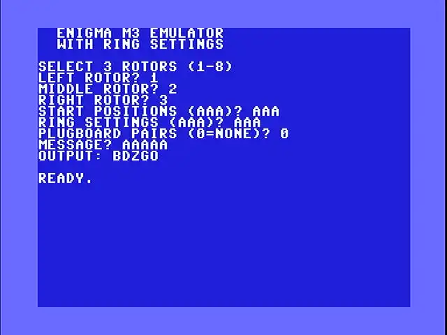
10 PRINT CHR$(147);" ENIGMA M3 EMULATOR"
20 PRINT " WITH RING SETTINGS":PRINT
100 DIM RF(7,25),RI(7,25),RE(25),PB(25)
110 FOR R=0 TO 7:FOR I=0 TO 25
120 READ RF(R,I):NEXT I,R
200 DATA 4,10,12,5,11,6,3,16,21,25
210 DATA 13,19,14,22,24,7,23,20,18,15
220 DATA 0,8,1,17,2,9
230 DATA 0,9,3,10,18,8,17,20,23,1
240 DATA 11,7,22,19,12,2,16,6,25,13
250 DATA 15,24,5,21,14,4
260 DATA 1,3,5,7,9,11,2,15,17,19
270 DATA 23,21,25,13,24,4,8,22,6,0
280 DATA 10,12,20,18,16,14
290 DATA 4,18,14,21,15,25,9,0,24,16
300 DATA 20,8,17,7,23,11,13,5,19,6
310 DATA 10,3,2,12,22,1
320 DATA 21,25,1,17,6,8,19,24,20,15
330 DATA 18,3,13,7,11,23,0,22,12,9
340 DATA 16,14,5,4,2,10
350 DATA 9,15,6,21,14,20,12,5,24,16
360 DATA 1,4,13,7,25,17,3,10,0,18
370 DATA 23,11,8,2,19,22
380 DATA 13,25,9,7,6,17,2,23,12,24
390 DATA 18,22,1,14,20,5,0,8,21,11
395 DATA 15,4,10,16,3,19
400 DATA 5,10,16,7,19,11,23,14,2,1
410 DATA 9,18,15,3,25,17,0,12,4,22
420 DATA 13,8,20,24,6,21
450 REM COMPUTE INVERSE TABLES
460 FOR R=0 TO 7:FOR I=0 TO 25
470 RI(R,RF(R,I))=I
480 NEXT I,R
500 REM REFLECTOR UKW-B
510 FOR I=0 TO 25:READ RE(I):NEXT
520 DATA 24,17,20,7,16,18,11,3,15,23
530 DATA 13,6,14,10,12,8,4,1,5,25
540 DATA 2,22,21,9,0,19
600 REM NOTCH POSITIONS (TWO PER ROTOR)
610 DIM NO(7,1)
620 NO(0,0)=16:NO(0,1)=-1
630 NO(1,0)=4:NO(1,1)=-1
640 NO(2,0)=21:NO(2,1)=-1
650 NO(3,0)=9:NO(3,1)=-1
660 NO(4,0)=25:NO(4,1)=-1
670 NO(5,0)=25:NO(5,1)=12
680 NO(6,0)=25:NO(6,1)=12
690 NO(7,0)=25:NO(7,1)=12
695 REM RING SETTINGS (0=A, 25=Z)
696 DIM RS(2)
700 FOR I=0 TO 25:PB(I)=I:NEXT
710 PRINT "SELECT 3 ROTORS (1-8)"
720 INPUT "LEFT ROTOR";RL
730 INPUT "MIDDLE ROTOR";RM
740 INPUT "RIGHT ROTOR";RR
750 RL=RL-1:RM=RM-1:RR=RR-1
760 INPUT "START POSITIONS (AAA)";PO$
770 LP=ASC(MID$(PO$,1,1))-65
780 MP=ASC(MID$(PO$,2,1))-65
790 RP=ASC(MID$(PO$,3,1))-65
791 INPUT "RING SETTINGS (AAA)";RS$
792 RS(0)=ASC(MID$(RS$,1,1))-65
793 RS(1)=ASC(MID$(RS$,2,1))-65
794 RS(2)=ASC(MID$(RS$,3,1))-65
800 INPUT "PLUGBOARD PAIRS (0=NONE)";NP
810 IF NP=0 THEN 860
820 FOR I=1 TO NP
830 PRINT "PAIR";I;
840 INPUT "(E.G. AB)";PP$
845 A=ASC(MID$(PP$,1,1))-65
850 B=ASC(MID$(PP$,2,1))-65
855 PB(A)=B:PB(B)=A:NEXT
860 INPUT "MESSAGE";MS$
870 PRINT "OUTPUT: ";
900 FOR CH=1 TO LEN(MS$)
910 GOSUB 2000
920 C=ASC(MID$(MS$,CH,1))-65
930 C=PB(C)
940 GOSUB 3000
950 C=PB(C)
960 PRINT CHR$(C+65);
970 NEXT
980 PRINT:END
2000 REM STEP ROTORS (RING-ADJUSTED)
2001 N1=NO(RM,0)-RS(1)+26
2002 N1=N1-INT(N1/26)*26
2003 N2=NO(RM,1)-RS(1)+26
2004 N2=N2-INT(N2/26)*26
2005 N3=NO(RR,0)-RS(2)+26
2006 N3=N3-INT(N3/26)*26
2007 N4=NO(RR,1)-RS(2)+26
2008 N4=N4-INT(N4/26)*26
2010 IF MP<>N1 AND MP<>N2 THEN 2040
2020 LP=LP+1:LP=LP-INT(LP/26)*26
2030 MP=MP+1:MP=MP-INT(MP/26)*26
2040 IF RP<>N3 AND RP<>N4 THEN 2060
2050 MP=MP+1:MP=MP-INT(MP/26)*26
2060 RP=RP+1:RP=RP-INT(RP/26)*26
2070 RETURN
3000 REM FORWARD THROUGH ROTORS (WITH RINGS)
3010 E=(C+RP-RS(2)+26):E=E-INT(E/26)*26
3020 C=RF(RR,E)
3030 C=(C-RP+RS(2)+26):C=C-INT(C/26)*26
3040 E=(C+MP-RS(1)+26):E=E-INT(E/26)*26
3050 C=RF(RM,E)
3060 C=(C-MP+RS(1)+26):C=C-INT(C/26)*26
3070 E=(C+LP-RS(0)+26):E=E-INT(E/26)*26
3080 C=RF(RL,E)
3090 C=(C-LP+RS(0)+26):C=C-INT(C/26)*26
3100 REM REFLECTOR
3110 C=RE(C)
3120 REM INVERSE THROUGH ROTORS (WITH RINGS)
3130 E=(C+LP-RS(0)+26):E=E-INT(E/26)*26
3140 C=RI(RL,E)
3150 C=(C-LP+RS(0)+26):C=C-INT(C/26)*26
3160 E=(C+MP-RS(1)+26):E=E-INT(E/26)*26
3170 C=RI(RM,E)
3180 C=(C-MP+RS(1)+26):C=C-INT(C/26)*26
3190 E=(C+RP-RS(2)+26):E=E-INT(E/26)*26
3200 C=RI(RR,E)
3210 C=(C-RP+RS(2)+26):C=C-INT(C/26)*26
3220 RETURN
Assembly Changes
The assembly version needs three new storage bytes for ring settings and changes to two routines: rotor_pass and step.
Configuration
Three new bytes in the configuration section:
; ring settings (0=a, 25=z)
right_ring .byte 0
mid_ring   .byte 0
left_ring  .byte 0
We also need a zero page byte to pass the ring value into rotor_pass:
ring_val = $ff
rotor_pass
The original rotor_pass added the position on entry and subtracted it on exit. Now it also subtracts the ring on entry and adds it on exit:
; a = letter, x = position
; ring_val = ring setting
; ptr = wiring table
rotor_pass
          stx temp
          clc
          adc temp        ; + position (0-50)
          jsr mod26       ; reduce to 0-25
          sec
          sbc ring_val    ; - ring
          clc
          adc #26         ; ensure positive (1-51)
          jsr mod26       ; 0-25
          tay
          lda (ptr),y
          sec
          sbc temp        ; - position
          clc
          adc #26         ; ensure positive (1-51)
          jsr mod26       ; 0-25
          clc
          adc ring_val    ; + ring (0-50)
          jsr mod26       ; 0-25
          rts
We split the original two mod26 calls into four. Each call keeps its input in the 0-51 range, which is what mod26 needs (a single compare-and-subtract). Without the intermediate reductions, letter + position - ring + 26 could reach 76, which our one-pass mod26 can’t handle. With ring=0, the extra calls are harmless and the output matches the original emulator exactly.
encrypt
Before each jsr rotor_pass, we load the appropriate ring value into ring_val:
          ; right fwd
          ldx right_sel
          jsr set_fwd
          ldy right_ring
          sty ring_val
          ldx right_pos
          jsr rotor_pass

          ; middle fwd
          ldx mid_sel
          jsr set_fwd
          ldy mid_ring
          sty ring_val
          ldx mid_pos
          jsr rotor_pass
The same pattern repeats for all six rotor passes (three forward, three inverse). Each one loads its rotor’s ring value before calling rotor_pass.
step
The step routine needs to adjust each notch position by the ring before comparing. Here’s the middle rotor’s first notch check:
step
          ; double step?
          ldx mid_sel
          lda notch1,x
          sec
          sbc mid_ring
          clc
          adc #26
          jsr mod26
          cmp mid_pos
          beq do_double
Instead of comparing the raw notch value against the position, we compute (notch - ring + 26) mod 26 first. The same adjustment applies to the second notch check and both notch checks for the right rotor.
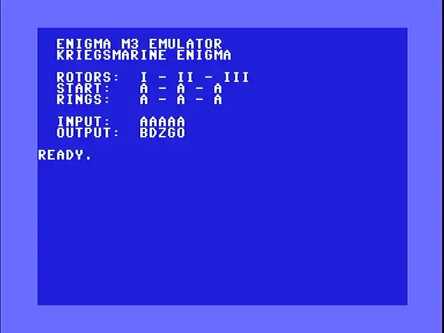
Here’s the whole thing. It assembles at $c000 and runs with sys 49152. The rotor wiring tables are identical to the emulator. What’s new: ring_val in zero page, three ring configuration bytes, a ring display block on screen, and the modified encrypt, rotor_pass, and step routines.
; ==============================
; enigma m3 - commodore 64
; with ring settings
; kriegsmarine, rotors i-viii
; ukw-b reflector
; turbo macro pro / tmpx
; by michael doornbos 2026
; mike@imapenguin.com
;
; .null/.text = screen codes
; use .byte for petscii strings
; ==============================

* = $c000

; --- zero page ---
; ptr = table pointer (2 bytes)
ptr       = $50
right_pos = $fb
mid_pos   = $fc
left_pos  = $fd
temp      = $fe
ring_val  = $ff

chrout    = $ffd2

; --- entry point ---
          ; cls, white text
          lda #$93
          jsr chrout
          lda #5
          jsr chrout
          lda #13
          jsr chrout

          ldx #<s_title
          ldy #>s_title
          jsr print
          lda #13
          jsr chrout
          ldx #<s_sub
          ldy #>s_sub
          jsr print
          lda #13
          jsr chrout
          lda #13
          jsr chrout

          ; show rotors
          ldx #<s_rotor
          ldy #>s_rotor
          jsr print
          ldx left_sel
          jsr print_rn
          ldx #<s_sep
          ldy #>s_sep
          jsr print
          ldx mid_sel
          jsr print_rn
          ldx #<s_sep
          ldy #>s_sep
          jsr print
          ldx right_sel
          jsr print_rn
          lda #13
          jsr chrout

          ; show positions
          ldx #<s_start
          ldy #>s_start
          jsr print
          lda init_lpos
          clc
          adc #65
          jsr chrout
          ldx #<s_sep
          ldy #>s_sep
          jsr print
          lda init_mpos
          clc
          adc #65
          jsr chrout
          ldx #<s_sep
          ldy #>s_sep
          jsr print
          lda init_rpos
          clc
          adc #65
          jsr chrout
          lda #13
          jsr chrout

          ; show rings
          ldx #<s_rings
          ldy #>s_rings
          jsr print
          lda left_ring
          clc
          adc #65
          jsr chrout
          ldx #<s_sep
          ldy #>s_sep
          jsr print
          lda mid_ring
          clc
          adc #65
          jsr chrout
          ldx #<s_sep
          ldy #>s_sep
          jsr print
          lda right_ring
          clc
          adc #65
          jsr chrout
          lda #13
          jsr chrout
          lda #13
          jsr chrout

          ; show input
          ldx #<s_input
          ldy #>s_input
          jsr print
          ldx #0
pmsgloop  lda message,x
          beq pmsgdone
          stx temp
          jsr chrout
          ldx temp
          inx
          jmp pmsgloop
pmsgdone  lda #13
          jsr chrout

          ; output label
          ldx #<s_out
          ldy #>s_out
          jsr print

          ; init positions
          lda init_rpos
          sta right_pos
          lda init_mpos
          sta mid_pos
          lda init_lpos
          sta left_pos

          ; encrypt each char
          ldx #0
msgloop   lda message,x
          beq msgdone
          stx savex
          sec
          ; a=0..z=25
          sbc #65
          jsr encrypt
          clc
          adc #65
          jsr chrout
          ldx savex
          inx
          jmp msgloop
msgdone   lda #13
          jsr chrout
          rts

savex     .byte 0
; "aaaaa"
message   .byte 65,65,65,65,65,0

; --- configuration ---
; select (0=i, 7=viii)
right_sel .byte 2     ; iii
mid_sel   .byte 1     ; ii
left_sel  .byte 0     ; i
; positions (0=a, 25=z)
init_rpos .byte 0
init_mpos .byte 0
init_lpos .byte 0
; ring settings (0=a, 25=z)
right_ring .byte 0
mid_ring   .byte 0
left_ring  .byte 0

; notch positions per rotor
; $ff = no second notch
notch1    .byte 16,4,21,9
          .byte 25,25,25,25
notch2    .byte $ff,$ff,$ff,$ff
          .byte $ff,12,12,12

; --- strings (petscii) ---
; "  enigma m3 emulator"
s_title   .byte 32,32,69,78,73,71
          .byte 77,65,32,77,51,32
          .byte 69,77,85,76,65,84
          .byte 79,82,0
; "  kriegsmarine enigma"
s_sub     .byte 32,32,75,82,73,69
          .byte 71,83,77,65,82,73
          .byte 78,69,32,69,78,73
          .byte 71,77,65,0
; "  rotors:  "
s_rotor   .byte 32,32,82,79,84,79
          .byte 82,83,58,32,32,0
; "  start:   "
s_start   .byte 32,32,83,84,65,82
          .byte 84,58,32,32,32,0
; "  rings:   "
s_rings   .byte 32,32,82,73,78,71
          .byte 83,58,32,32,32,0
; "  input:   "
s_input   .byte 32,32,73,78,80,85
          .byte 84,58,32,32,32,0
; "  output:  "
s_out     .byte 32,32,79,85,84,80
          .byte 85,84,58,32,32,0
; " - "
s_sep     .byte 32,45,32,0

; rotor names (petscii)
rn1       .byte 73,0
rn2       .byte 73,73,0
rn3       .byte 73,73,73,0
rn4       .byte 73,86,0
rn5       .byte 86,0
rn6       .byte 86,73,0
rn7       .byte 86,73,73,0
rn8       .byte 86,73,73,73,0
rn_lo     .byte <rn1,<rn2
          .byte <rn3,<rn4
          .byte <rn5,<rn6
          .byte <rn7,<rn8
rn_hi     .byte >rn1,>rn2
          .byte >rn3,>rn4
          .byte >rn5,>rn6
          .byte >rn7,>rn8

; --- print string ---
; x=lo, y=hi
print     stx ptr
          sty ptr+1
          ldy #0
ploop     lda (ptr),y
          beq pdone
          jsr chrout
          iny
          bne ploop
pdone     rts

; --- print rotor name ---
; x = rotor index (0-7)
print_rn
          lda rn_lo,x
          sta ptr
          lda rn_hi,x
          sta ptr+1
          ldy #0
rnloop    lda (ptr),y
          beq rndone
          jsr chrout
          iny
          bne rnloop
rndone    rts

; --- encrypt ---
; a = letter (0-25) in/out
encrypt   pha
          jsr step
          pla

          ; plugboard in
          tax
          lda plugboard,x

          ; right fwd
          ldx right_sel
          jsr set_fwd
          ldy right_ring
          sty ring_val
          ldx right_pos
          jsr rotor_pass

          ; middle fwd
          ldx mid_sel
          jsr set_fwd
          ldy mid_ring
          sty ring_val
          ldx mid_pos
          jsr rotor_pass

          ; left fwd
          ldx left_sel
          jsr set_fwd
          ldy left_ring
          sty ring_val
          ldx left_pos
          jsr rotor_pass

          ; reflector
          tax
          lda reflector,x

          ; left inv
          ldx left_sel
          jsr set_inv
          ldy left_ring
          sty ring_val
          ldx left_pos
          jsr rotor_pass

          ; middle inv
          ldx mid_sel
          jsr set_inv
          ldy mid_ring
          sty ring_val
          ldx mid_pos
          jsr rotor_pass

          ; right inv
          ldx right_sel
          jsr set_inv
          ldy right_ring
          sty ring_val
          ldx right_pos
          jsr rotor_pass

          ; plugboard out
          tax
          lda plugboard,x
          rts

; --- step rotors ---
; ring settings shift notch positions
step
          ; double step?
          ldx mid_sel
          lda notch1,x
          sec
          sbc mid_ring
          clc
          adc #26
          jsr mod26
          cmp mid_pos
          beq do_double
          ; check second notch
          lda notch2,x
          cmp #$ff
          beq chk_n2done
          sec
          sbc mid_ring
          clc
          adc #26
          jsr mod26
          cmp mid_pos
          beq do_double
chk_n2done
          ; right at notch?
          ldx right_sel
          lda notch1,x
          sec
          sbc right_ring
          clc
          adc #26
          jsr mod26
          cmp right_pos
          beq do_mid
          ; check second notch
          lda notch2,x
          cmp #$ff
          beq step_right
          sec
          sbc right_ring
          clc
          adc #26
          jsr mod26
          cmp right_pos
          beq do_mid
          jmp step_right
do_double
          ; step left+mid
          lda left_pos
          clc
          adc #1
          jsr mod26
          sta left_pos
          lda mid_pos
          clc
          adc #1
          jsr mod26
          sta mid_pos
          jmp step_right
do_mid
          lda mid_pos
          clc
          adc #1
          jsr mod26
          sta mid_pos
step_right
          ; always step right
          lda right_pos
          clc
          adc #1
          jsr mod26
          sta right_pos
          rts

; --- mod26 ---
mod26     cmp #26
          bcc m26done
          sbc #26
m26done   rts

; --- rotor pass (with ring) ---
; a = letter, x = position
; ring_val = ring setting
; ptr = wiring table
rotor_pass
          stx temp
          clc
          adc temp        ; + position (0-50)
          jsr mod26       ; reduce to 0-25
          sec
          sbc ring_val    ; - ring
          clc
          adc #26         ; ensure positive (1-51)
          jsr mod26       ; 0-25
          tay
          lda (ptr),y
          sec
          sbc temp        ; - position
          clc
          adc #26         ; ensure positive (1-51)
          jsr mod26       ; 0-25
          clc
          adc ring_val    ; + ring (0-50)
          jsr mod26       ; 0-25
          rts

; --- set table pointer ---
set_fwd   ldy fwd_lo,x
          sty ptr
          ldy fwd_hi,x
          sty ptr+1
          rts

set_inv   ldy inv_lo,x
          sty ptr
          ldy inv_hi,x
          sty ptr+1
          rts

; --- address tables ---
fwd_lo    .byte <rot1_f,<rot2_f
          .byte <rot3_f,<rot4_f
          .byte <rot5_f,<rot6_f
          .byte <rot7_f,<rot8_f
fwd_hi    .byte >rot1_f,>rot2_f
          .byte >rot3_f,>rot4_f
          .byte >rot5_f,>rot6_f
          .byte >rot7_f,>rot8_f
inv_lo    .byte <rot1_i,<rot2_i
          .byte <rot3_i,<rot4_i
          .byte <rot5_i,<rot6_i
          .byte <rot7_i,<rot8_i
inv_hi    .byte >rot1_i,>rot2_i
          .byte >rot3_i,>rot4_i
          .byte >rot5_i,>rot6_i
          .byte >rot7_i,>rot8_i

; === rotor wiring ===

; i: ekmflgdqvzntowyhxuspaibrcj
rot1_f    .byte 4,10,12,5,11,6
          .byte 3,16,21,25,13,19
          .byte 14,22,24,7,23,20
          .byte 18,15,0,8,1,17
          .byte 2,9

; ii: ajdksiruxblhwtmcqgznpyfvoe
rot2_f    .byte 0,9,3,10,18,8
          .byte 17,20,23,1,11,7
          .byte 22,19,12,2,16,6
          .byte 25,13,15,24,5,21
          .byte 14,4

; iii: bdfhjlcprtxvznyeiwgakmusqo
rot3_f    .byte 1,3,5,7,9,11
          .byte 2,15,17,19,23,21
          .byte 25,13,24,4,8,22
          .byte 6,0,10,12,20,18
          .byte 16,14

; iv: esovpzjayquirhxlnftgkdcmwb
rot4_f    .byte 4,18,14,21,15,25
          .byte 9,0,24,16,20,8
          .byte 17,7,23,11,13,5
          .byte 19,6,10,3,2,12
          .byte 22,1

; v: vzbrgityupsdnhlxawmjqofeck
rot5_f    .byte 21,25,1,17,6,8
          .byte 19,24,20,15,18,3
          .byte 13,7,11,23,0,22
          .byte 12,9,16,14,5,4
          .byte 2,10

; vi: jpgvoumfyqbenhzrdkasxlictw
rot6_f    .byte 9,15,6,21,14,20
          .byte 12,5,24,16,1,4
          .byte 13,7,25,17,3,10
          .byte 0,18,23,11,8,2
          .byte 19,22

; vii: nzjhgrcxmyswboufaivlpekqdt
rot7_f    .byte 13,25,9,7,6,17
          .byte 2,23,12,24,18,22
          .byte 1,14,20,5,0,8
          .byte 21,11,15,4,10,16
          .byte 3,19

; viii: fkqhtlxocbjspdzramewniuygv
rot8_f    .byte 5,10,16,7,19,11
          .byte 23,14,2,1,9,18
          .byte 15,3,25,17,0,12
          .byte 4,22,13,8,20,24
          .byte 6,21

; inverse tables

rot1_i    .byte 20,22,24,6,0,3
          .byte 5,15,21,25,1,4
          .byte 2,10,12,19,7,23
          .byte 18,11,17,8,13,16
          .byte 14,9

rot2_i    .byte 0,9,15,2,25,22
          .byte 17,11,5,1,3,10
          .byte 14,19,24,20,16,6
          .byte 4,13,7,23,12,8
          .byte 21,18

rot3_i    .byte 19,0,6,1,15,2
          .byte 18,3,16,4,20,5
          .byte 21,13,25,7,24,8
          .byte 23,9,22,11,17,10
          .byte 14,12

rot4_i    .byte 7,25,22,21,0,17
          .byte 19,13,11,6,20,15
          .byte 23,16,2,4,9,12
          .byte 1,18,10,3,24,14
          .byte 8,5

rot5_i    .byte 16,2,24,11,23,22
          .byte 4,13,5,19,25,14
          .byte 18,12,21,9,20,3
          .byte 10,6,8,0,17,15
          .byte 7,1

rot6_i    .byte 18,10,23,16,11,7
          .byte 2,13,22,0,17,21
          .byte 6,12,4,1,9,15
          .byte 19,24,5,3,25,20
          .byte 8,14

rot7_i    .byte 16,12,6,24,21,15
          .byte 4,3,17,2,22,19
          .byte 8,0,13,20,23,5
          .byte 10,25,14,18,11,7
          .byte 9,1

rot8_i    .byte 16,9,8,13,18,0
          .byte 24,3,21,10,1,5
          .byte 17,20,7,12,2,15
          .byte 11,4,22,25,19,6
          .byte 23,14

; ukw-b: yruhqsldpxngokmiebfzcwvjat
reflector .byte 24,17,20,7,16,18
          .byte 11,3,15,23,13,6
          .byte 14,10,12,8,4,1
          .byte 5,25,2,22,21,9
          .byte 0,19

; plugboard (identity = no swaps)
plugboard .byte 0,1,2,3,4,5,6,7,8,9
          .byte 10,11,12,13,14,15
          .byte 16,17,18,19,20,21
          .byte 22,23,24,25
Testing
Set all ring settings to A (0) and you should get the same output as the original emulator. Rotors I-II-III at positions AAA with rings AAA: AAAAA encrypts to BDZGO. That hasn’t changed.
Now set rings to B-C-D (1-2-3) with everything else the same. AAAAA should encrypt to HYUWQ. A completely different result from the same input, same rotors, same starting positions. The only difference is three ring offsets.
Verify self-reciprocal behavior: encrypt HYUWQ with the same settings and you should get AAAAA back. If you don’t, something is wrong with the ring math.
You can check your output against the Cryptii Enigma simulator. Select M3, Rotors I-II-III, set the ring settings to B-C-D (or 02-03-04 in their 1-indexed notation), positions A-A-A, no plugboard cables.
The Keyspace Problem
In the cracker article, we searched 5,909,376 candidates (336 rotor orderings times 17,576 starting positions) and found the answer in about 22 minutes. That was without ring settings.
Ring settings add another factor of 26 x 26 x 26 = 17,576. For each rotor ordering and each starting position, there are now 17,576 possible ring combinations to try.
| Configuration | Orderings | Positions | Rings | Total |
|---|---|---|---|---|
| Without rings | 336 | 17,576 | 1 | 5,909,376 |
| With rings | 336 | 17,576 | 17,576 | ~103.9 billion |
That’s a factor of 17,576 increase. At the cracker’s speed of about 4,500 candidates per second (5.9 million in 22 minutes), searching 103.9 billion candidates would take roughly 23 million seconds. That’s about 267 days of continuous running.
Even splitting the work across ten C64s gives you 27 days each. A hundred C64s still means nearly three days per machine. Brute force doesn’t scale when the search space grows by four orders of magnitude.
This is why the Allies didn’t just try every setting. Turing’s Bombe used logical contradictions to eliminate impossible configurations without testing them one at a time. Instead of testing 103 billion candidates one by one, it ruled out huge swaths of the search space at once by finding contradictions in the wiring.
Extra Credit
A few things to explore on your own:
-
Ring setting search: If you know the rotor ordering and approximate starting positions (from context like message timestamps), you can search just the 17,576 ring combinations. That’s back to single-digit minutes on the C64.
-
Ring setting shortcuts: In practice, the right rotor’s ring setting is the hardest to recover because it moves with every keypress. The left rotor’s ring barely matters for short messages because it rarely steps. Some attacks fix the left ring at A and search only the middle and right rings (676 combinations instead of 17,576).
-
Display the rings: The assembly version already prints ring settings on screen. Write a BASIC front-end that POKEs ring values into
right_ring,mid_ring, andleft_ringbefore callingsys 49152, so you can experiment without reassembling.
The Enigma pin photo in the cover image is By Bob Lord - [1], uploaded in english wikipedia on 16. Feb. 2005 by en:User:Matt Crypto, CC BY-SA 3.0, https://commons.wikimedia.org/w/index.php?curid=258973